Electric Dollar Store
How to
This page has notes on how to use and work with the I²C modules.
Attaching headers
The castelled edge connector of the standard module is designed for either header or direct-to-board soldering. The pins have standard 0.1 inch spacing, so fit popular headers and solderless breadboards.
We stock 10-packs of 4-pin right angle headers: hdrs.
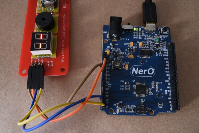
Using with Arduino
Connect the module to the Arduino as follows:
| module | Arduino |
|---|---|
| GND | GND |
| VCC | 3.3V |
| SDA | A4 |
| SCL | A5 |
Arduino requires external pull-up resistors with I²C.
For example you can use
4k7 with
br3.
Arduino sample code is given for each module. All the samples are here.
Soldering to a board
The four castellated holes on each module form a solder cup when held in place on a board like
br3.
Apply heat to the cup while adding solder.
You can use tape to hold the module in place during soldering.

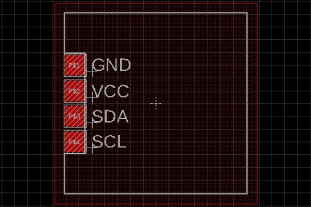
CADSoft Eagle footprint
The module footprint for Eagle is available
here.
I²C address solder links
The solder links at the edge of many modules allow you to change the I²C address of the module.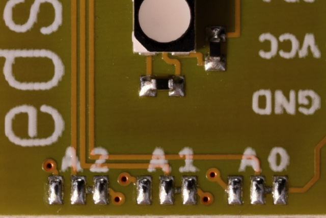 Each link controls one bit of the address. A0 is the least-significant bit of the address, and so on.
By default each link is connected to ground, the right-hand side connection.
This sets the corresponding address bit to zero.
By breaking the link and connecting it to the left-hand side block,
you set the corresponding address bit to one.
Sparkfun has a
tutorial
on working with this kind of solder jumper.
Remember that after you have changed the I²C address,
you will need to update any code to use the new address.
Each link controls one bit of the address. A0 is the least-significant bit of the address, and so on.
By default each link is connected to ground, the right-hand side connection.
This sets the corresponding address bit to zero.
By breaking the link and connecting it to the left-hand side block,
you set the corresponding address bit to one.
Sparkfun has a
tutorial
on working with this kind of solder jumper.
Remember that after you have changed the I²C address,
you will need to update any code to use the new address.